This and few other subsequent posts will explore the diagrams used in designing the application in developing the Logical model for application.
This post explores the ORM(Object Role Modelling)
Object Role Modeling (ORM):
An ORM diagram includes the primary objects (also called entities) in the system, the relationships between those objects, and the attributes (and even attribute values) that define those objects. ORM notation is used to create this logical representation between objects.
ORM Objects
In ORM diagrams, each object is represented by an oval containing the name of that object.
Simple rule to identify ORM objects: Any nouns in the requirements or use case is an ORM object
ORM Relationship
An ORM relationship defines how two or more objects are related to one another. In an ORM, a relationship between objects is represented as a line connecting the objects. Along this line will be a rectangle divided into segments based on the number of objects in the relationship. This is typically two segments because most often, you are modeling relationships between two objects (called a binary relationship). However, if you are modeling a relationship that exists among three objects (called a ternary relationship); all three relationships need to be defined
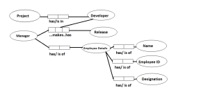
Project and developer has a binary relationship. A developer can be assigned to a Project.
Ternary relationship exists between Release, manager and developer. A release consists of efforts from developer(s) and manager.
ORM Facts
A fact indicates how two (or more) items are related. This is also called the fact model for the application. They represent how objects really relate to one another.

The Facts depicted in figure can be read as;
A project has developer and in reverse Developer is in Project
For Ternary relation Developer and Project manager makes a release and reversely a Release has a manager and developer(s).
Similarly, a Manager has Employee details and Employee Details is of manager.
An employee detail has a Name, EmployeeID and Designation and Designation, EmployeeID and Name is of Employee details (that is a manager).
ORM Constraints
ORM constraints define how the objects participate in the relationship. This includes defining which objects are mandatory and the multiplicity of the relationship. Mandatory objects in a relationship are indicated by a closed (or filled) circle attached to either end of the connection. This closed circle indicates that the given object is mandatory in the relationship. That is, the related object does not exist without this object.
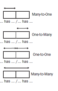
Multiplicity indicates whether two objects relate to one another as one-to-one, one-to-many, or many-to-many. Multiplicity is indicated with a series of arrows over the relationship shape.
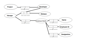
In the Above figures, the objects are mandatory; however No Color has been used for Filling.
The Figure below depicts the Multiplicity notation(s).
Try to put these constraints in the Figure-1 or Figure-2 to get the complete picture of ORM diagram. This has been left intentionally as a practice to the reader.
Note: ORM diagrams, as a myth are thought to be used in Database diagramming only, however it serves as an excellent tool for initial designing phase(s).
The next few post will cover the other diagramming techniques that include component diagram, class diagram, activity diagram, Sequence diagram, collaboration diagrams.
Hope this article was helpful….
Till Next we connect…….
Happy Learning.
This post explores the ORM(Object Role Modelling)
Object Role Modeling (ORM):
An ORM diagram includes the primary objects (also called entities) in the system, the relationships between those objects, and the attributes (and even attribute values) that define those objects. ORM notation is used to create this logical representation between objects.
ORM Objects
In ORM diagrams, each object is represented by an oval containing the name of that object.
Simple rule to identify ORM objects: Any nouns in the requirements or use case is an ORM object
ORM Relationship
An ORM relationship defines how two or more objects are related to one another. In an ORM, a relationship between objects is represented as a line connecting the objects. Along this line will be a rectangle divided into segments based on the number of objects in the relationship. This is typically two segments because most often, you are modeling relationships between two objects (called a binary relationship). However, if you are modeling a relationship that exists among three objects (called a ternary relationship); all three relationships need to be defined
Project and developer has a binary relationship. A developer can be assigned to a Project.
Ternary relationship exists between Release, manager and developer. A release consists of efforts from developer(s) and manager.
ORM Facts
A fact indicates how two (or more) items are related. This is also called the fact model for the application. They represent how objects really relate to one another.

The Facts depicted in figure can be read as;
A project has developer and in reverse Developer is in Project
For Ternary relation Developer and Project manager makes a release and reversely a Release has a manager and developer(s).
Similarly, a Manager has Employee details and Employee Details is of manager.
An employee detail has a Name, EmployeeID and Designation and Designation, EmployeeID and Name is of Employee details (that is a manager).
ORM Constraints
ORM constraints define how the objects participate in the relationship. This includes defining which objects are mandatory and the multiplicity of the relationship. Mandatory objects in a relationship are indicated by a closed (or filled) circle attached to either end of the connection. This closed circle indicates that the given object is mandatory in the relationship. That is, the related object does not exist without this object.
Multiplicity indicates whether two objects relate to one another as one-to-one, one-to-many, or many-to-many. Multiplicity is indicated with a series of arrows over the relationship shape.
In the Above figures, the objects are mandatory; however No Color has been used for Filling.
The Figure below depicts the Multiplicity notation(s).
Try to put these constraints in the Figure-1 or Figure-2 to get the complete picture of ORM diagram. This has been left intentionally as a practice to the reader.
Note: ORM diagrams, as a myth are thought to be used in Database diagramming only, however it serves as an excellent tool for initial designing phase(s).
The next few post will cover the other diagramming techniques that include component diagram, class diagram, activity diagram, Sequence diagram, collaboration diagrams.
Hope this article was helpful….
Till Next we connect…….
Happy Learning.

Try to put these constraints in the Figure-1 or Figure-2 to get the complete picture of ORM diagram. This has been left intentionally as a practice to the reader.
Note: ORM diagrams, as a myth are thought to be used in Database diagramming only, however it serves as an excellent tool for initial designing phase(s).
The next few post will cover the other diagramming techniques that include component diagram, class diagram, activity diagram, Sequence diagram, collaboration diagrams.
Hope this article was helpful….
Till Next we connect…….
Happy Learning.

Comments
Post a Comment