Sequence Diagram
Sequence diagram shows object interaction during execution (or run time). The model demonstrates the lifetime of these objects and shows the message exchange between them.
The UML notations are critical in sequence diagrams.
Objects are listed as rectangles at the top of the diagram with lifelines extending from them.
An object lifeline is an indication of how long an object will live before it is disposed of or made ready for garbage collection. The objects themselves are described in the rectangle that sits atop this lifeline. The description that goes in the rectangle is meant to describe an instance of the class. Description is written as an Object or the Object, where the object is the name of the class or variable representing the class.
The long rectangles that extend along the lifeline of each object indicate when an object is created and when it goes out of scope.
The messages that pass between objects are indicated by the arrows from one lifeline to another. These messages are meant to be read from top to bottom and left to right (as a sequence). Each message represents a method call, property call, or return value.
Return calls are shown as a dashed arrow
Asynchronous messages are demonstrated by using an arrow that has only its lower half.
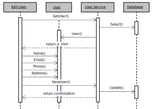
The Following Diagram depicts the theory covered above.

Here, we have 4 objects EditUser, User, UserService and a database.
The GUI contains Edit User functionality and the internal processing done when editing user is shown above.
Following are some other links that can be used as reference.
Link1
Link2
Hope this was useful…..
Till Next we connect…..
Happy Learning
Sequence diagram shows object interaction during execution (or run time). The model demonstrates the lifetime of these objects and shows the message exchange between them.
The UML notations are critical in sequence diagrams.
Objects are listed as rectangles at the top of the diagram with lifelines extending from them.
An object lifeline is an indication of how long an object will live before it is disposed of or made ready for garbage collection. The objects themselves are described in the rectangle that sits atop this lifeline. The description that goes in the rectangle is meant to describe an instance of the class. Description is written as an Object or the Object, where the object is the name of the class or variable representing the class.
The long rectangles that extend along the lifeline of each object indicate when an object is created and when it goes out of scope.
The messages that pass between objects are indicated by the arrows from one lifeline to another. These messages are meant to be read from top to bottom and left to right (as a sequence). Each message represents a method call, property call, or return value.
Return calls are shown as a dashed arrow
Asynchronous messages are demonstrated by using an arrow that has only its lower half.
The Following Diagram depicts the theory covered above.

Here, we have 4 objects EditUser, User, UserService and a database.
The GUI contains Edit User functionality and the internal processing done when editing user is shown above.
Following are some other links that can be used as reference.
Link1
Link2
Hope this was useful…..
Till Next we connect…..
Happy Learning
Comments
Post a Comment