component diagrams
A component diagram is used to indicate the components (or code packages) that will be created for the application. A component is made up of logically related classes grouped together in a single deployable unit (consider them the DLLs or Web services).
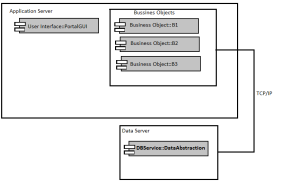
The components are represented by the rectangles that include the two smaller rectangles on their left, as depicted below.

Each component name is preceded with text, indicating its logical layer, and then two colons. This text represents the components package.
The outer boxes that surround the components are called nodes.
All this is demonstrated in the figure below.

Class Diagrams is another diagram that can be created easily using Visual Studio and id the most commonly used diagram and would not be covered here.
Next post will cover Sequence Diagram.
Till next we connect……
Happy Learning.
A component diagram is used to indicate the components (or code packages) that will be created for the application. A component is made up of logically related classes grouped together in a single deployable unit (consider them the DLLs or Web services).
The components are represented by the rectangles that include the two smaller rectangles on their left, as depicted below.

Each component name is preceded with text, indicating its logical layer, and then two colons. This text represents the components package.
The outer boxes that surround the components are called nodes.
All this is demonstrated in the figure below.

Class Diagrams is another diagram that can be created easily using Visual Studio and id the most commonly used diagram and would not be covered here.
Next post will cover Sequence Diagram.
Till next we connect……
Happy Learning.
Comments
Post a Comment